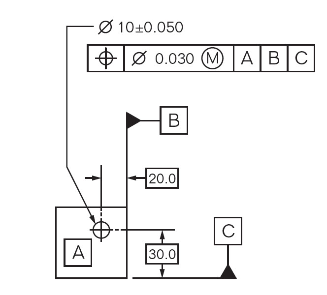
Start studying fanuc section 2 - handling tool operations and programming. Learn vocabulary, terms, and more with flashcards, games, and other study tools. True Position GD&T Tolerance Calculator True position tolerance MMC is used as a geometric dimensioning and tolerancing (GD&T) location control over the electrical engineers design and drawings. It is useful for building electrical tools such like printed circuit boards and associated mechanical components. True Position Tools cabinet hardware jigs, LED installation jigs, rigid plastic cases, drill bits, accessories and more. True Position Tools cabinet hardware jigs, LED installation jigs, rigid plastic cases, drill bits, accessories and more.

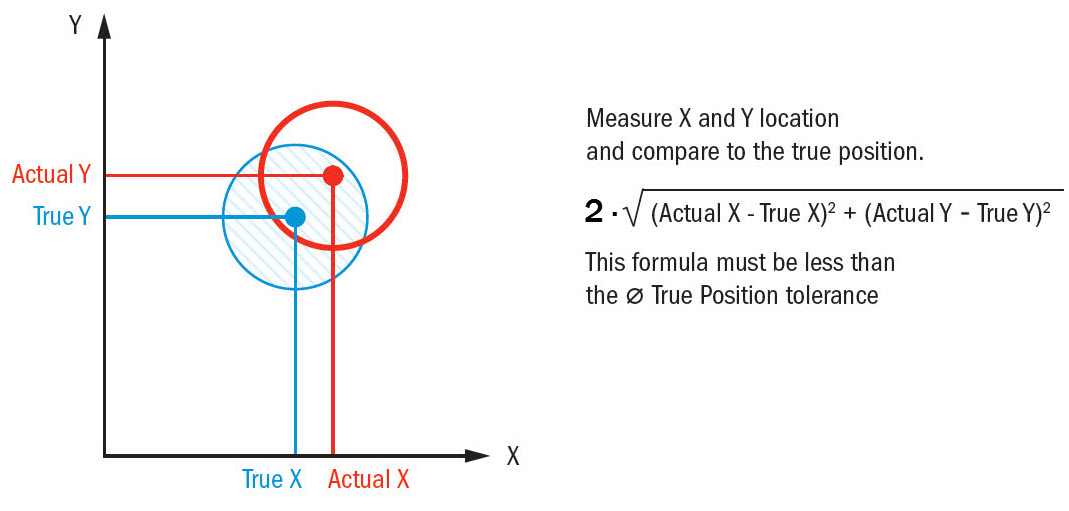
The basic formula for True Position is 2 x the square root of the deviation in one axis squared + the deviation in the other axis squared.True Position = 2√ Deviation in X² + Deviation in Y²It's hard to convey a good example of the formula with the font limitation of this forum. However, the X & Y axis’ are for a feature measured in the Z axis plane. If you measure in the X axis plane, you would substitute the X² with Z².
If you measure in the Y axis you would substitute the Y² with Z².Subsequently, if there is a MMC modifier in the call out you would be allowed bonus tolerance. As long as you do NOT have any modifiers (meaning the tolerance, as well as the datums are at RFS (Regardless of Feataure Size)), you can do the math by hand.
True Position Bonus Tolerance Calculator
Even a modifier on the tolerance is still quite easy to calculate.The moment you at a modifier on the datums though, things get complicated immediately. I agree with Mat, it can take pages to figure it out by hand.I have done many experiements using modifiers on datums using PC-DMIS V4.1, comparing it to hand estimates. Generally, I think that they calculate it correctly. You have to use the new Xactmeasure GD&T to get it right.
I believe it does not work using the legacy dimensioning.Jan. The basic formula for True Position is 2 x the square root of the deviation in one axis squared + the deviation in the other axis squared.True Position = 2√ Deviation in X² + Deviation in Y²It's hard to convey a good example of the formula with the font limitation of this forum. However, the X & Y axis’ are for a feature measured in the Z axis plane. If you measure in the X axis plane, you would substitute the X² with Z². If you measure in the Y axis you would substitute the Y² with Z².Subsequently, if there is a MMC modifier in the call out you would be allowed bonus tolerance. This is a good 2 dimensional true position calculator. Thanks for all the good replies guys.


I screwed my knee up last Thursday and just got back to work today.Wish I could post a pic but can't. I'll try it this way:the call out is: t/p dia.015 to f d & eWe make landing gear for large airplanes so everything is round and cyclindrical(sp).The part is shaped like a cyclinder, open on one end (the face on that end happens to be datum -e-), closed on the other end with a lug w/an approx.
4.5' hole running perpendicular to the cyclinder. Clear as mud?The C/L of the cyclinder is datum -d- with the face of the lug being designated as datum -f. All datums are listed as RFS.It was my understanding that you simply added the third datum to the equation as Matt has shown.
My partner in crime here on the 2nd shift was under the impression that there was a lot more to it than that.Thanks again. I can always count on you guys for the help.